A wiring diagram is a drawing that shows how electrical components are connected together. It can be used to troubleshoot problems with the electrical system. The IH 574 starter wiring diagram helps to troubleshoot your issues easily.
So, if you’re looking for a starter wiring diagram for your IH 574 tractor, you’ve come to the right place. This article will provide a detailed description of the starter wiring diagram and step-by-step instructions for adequately wiring your IH 574 tractor.
The IH 574 Starter Wiring Diagram

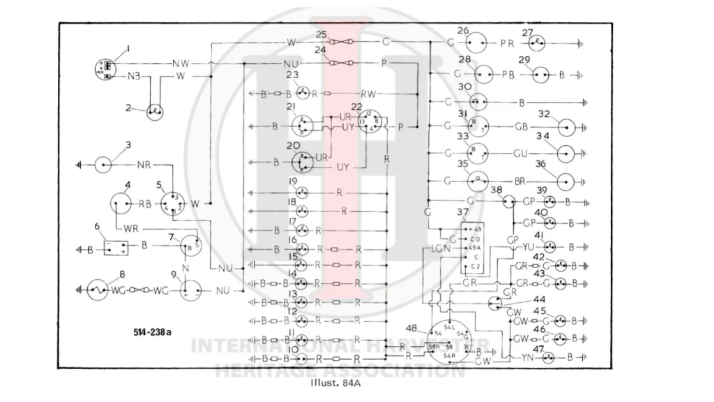
To know the location and description of the IH 574 starter wiring diagram, we will show a detailed drawing below. Although it is not mentioned, the IH 574 starter wiring diagram is located in the engine compartment on the left side of the engine near the battery.
The IH 574 starter wiring diagram consists of two main parts: the power and ground cables. The power cable is red and connects to the positive terminal of the battery. The ground cable is black and connects to the negative terminal of the battery.
The IH 574 starter wiring diagram also includes a fuse box. The fuse box is located in the engine compartment on the right side of the engine near the firewall. The fuse box contains fuses for the headlights, taillights, and other accessories.
The IH 574 Wiring Diagram Parts List
1. Alternator: An alternator is a device that produces alternating current (AC) from direct current (DC) by using a commutator. A common type of alternator is the three-phase alternator, which uses three wires to connect to the three main electrical phases. The circuit comprises three main wires: battery positive cable, voltage sensing wire, and ignition wire. The ignition input wire is attached to the engine.
2. Alternator warning light: The wire runs from the console to the warning light mounted in the dashboard.
3. Thermostat: Thermostat wiring involves multiple strands of coated copper wire laid out individually and wrapped in protective insulation. During the installation process, the wires are attached to a board and convey data to each wire by a voltage source such as a thermostat or low voltage device.
4. Safety start switch: The switch prevents the engine from starting unless the gear selector is in the park or neutral position. This prevents the engine from starting automatically either in drive or reverse gear.
5. Keyswitch: A key block is a mechanism consisting of a key that can be activated to perform a particular job.
6. Battery: Provide direct power to the engine.
7. Starting motor: Helps to move the engine starting parts.
8. Cigar lighter: The heating element emits a very hot orange glow soon, causing the bimetallic strip to buckle and release the mechanism. The handle sticks out, eliminating the need for the user to time the heating operation. If the lighter is then quickly removed from the socket, it can operate as a cigarette lighter, cigar lighter, or fuse.
9. Ammeter: A resistance on an ammeter is very low, so it will connect in series with the load without altering the current.
10. 2-pin power socket: The establishment of the power outlet indicates that it is not grounded and it usually has two pins that transmit electric current. Originally, all electrical devices were equipped with 2-pole plugs, so it was generally assumed that all power sockets were 2-pole ports.
11. Left tail light: They are in red color, when the vehicle is in reverse they light up.
12. Left side light: Parking light.
13. Right side lights: Parking light.
14. Right tail lights: They are in red color, when the vehicle is in reverse they light up.
15. Number plate light: Allowing vehicles to see the distance/
16. Speedometer light: Helps to see the vehicle’s speed.
17. Tachometer light: Digital displace light.
18. Right panel light: Helps to see the right panel.
19. Left panel light: Helps to see the left panel.
20. Left headlight: Helps to see the left side road.
21. Right headlight: Helps to see the left side road.
22. Light switch
23. Plough light
24. Fuse 50 amp
25. Fuse 25 amp
26. Parking brake switch
27. Parking brake warning light
28. Horn
29. Horn button
30. Windscreen wiper
31. Fuel gauge
32. Fuel gauge transmitter
33. Heat indicator
34. Heat indicator transmitter
35. Transmission oil warning light
36. Oil warning light transmitter * Combined lights on crown-type fenders. ** Not included with de luxe wiring.
37. Flasher unit 38. Brake switch
39. Right brake light
40. Left brake light
Additional 574 Wiring Diagram Parts List
41. Trailer indicator warning light
42. Left front direction indicator
43. Left rear direction indicator
44. Direction indicator switch
45. Right front direction indicator
46. Right rear direction indicator
47. Tractor indicator warning light
48. 7-pin socket
Cable Color Code
- B Black
- U Blue
- N Brown
- G Green
- S Slate
- K Pink
- L Light
- W White
- P Purple
- M Medium
- Y Yellow
- R Red
- O Orange
- D Dark
IH 574 Tractor Maintenance
IH 574 tractor maintenance is important for anyone who owns this type of equipment. By keeping up with the recommended service schedule, you can avoid serious problems and expensive repairs. Here are five tips to help you keep your IH 574 running like new:
1. Check the engine oil level regularly and change it according to the manufacturer’s recommendations.
2. Keep the cooling system clean and free of leaks.
3. Keep the air filter clean at all times.
4. Keep the hydraulic oil level in the reservoir between FULL and ADD.
5. Keep the tires properly inflated and replace them when necessary.
6. Have your IH 574 tractor serviced regularly by a qualified professional.
Final Thoughts
In conclusion, the IH 574 starter wiring diagram is a great resource for anyone looking to wire their own tractor. With clear and concise instructions, it is easy to follow and get the job done right.
Related Posts:


![Gravely Drive Belt Diagram Guide for Easy Maintenance [Step-by-Step] 10 Gravely Drive Belt Diagram Guide for Easy Maintenance [Step-by-Step] 7](https://mowerslab.com/wp-content/uploads/2023/09/Gravely-Drive-Belt-Diagram-150x150.webp)
